Hot-cold high-availability deployment for Corda Enterprise
Overview

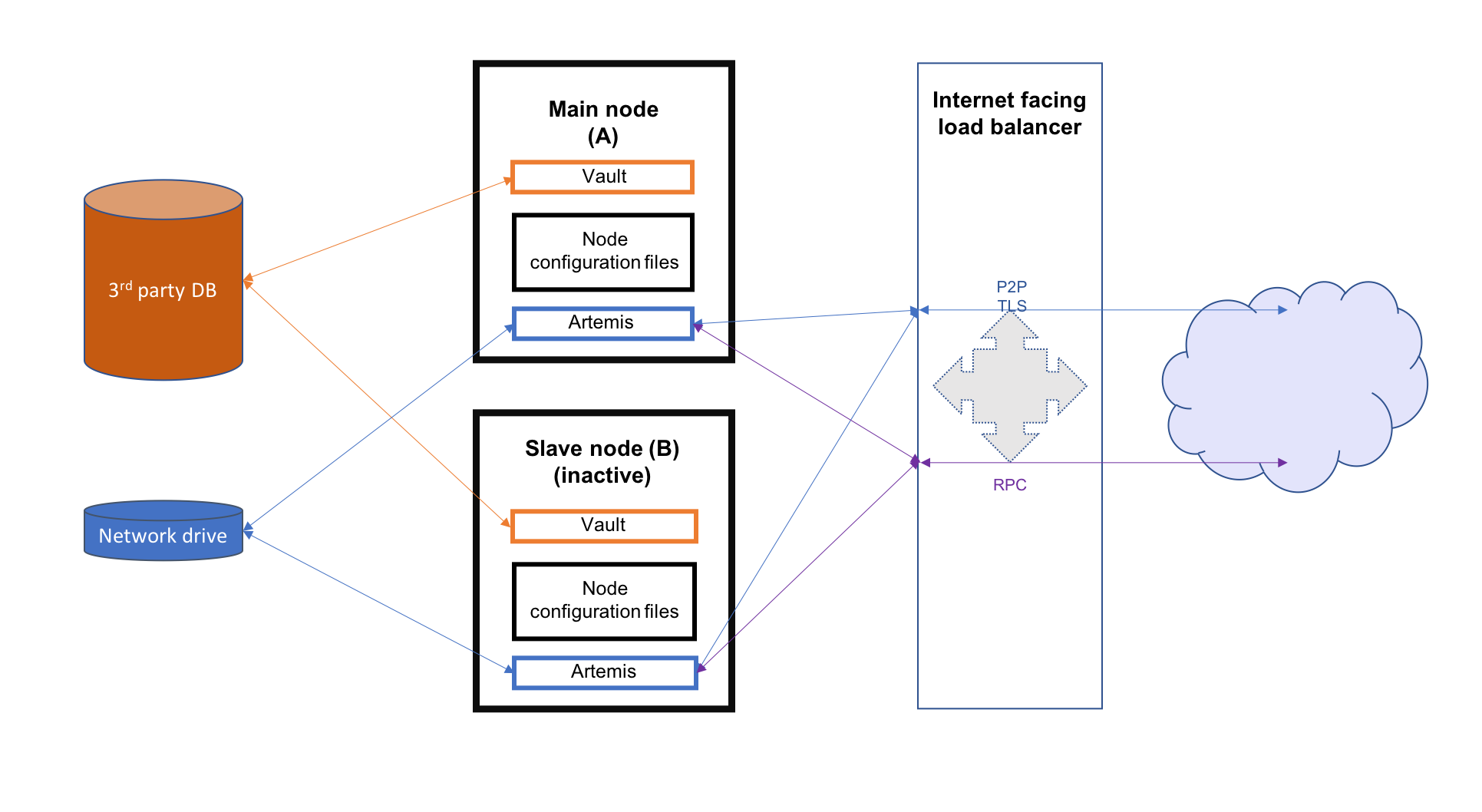
This section describes hot-cold availability of Corda Enterprise nodes and their associated configuration setup. In such a set-up, there is one back-up instance that can be started if the primary instance stops. Each instance of Corda should be hosted on a separate server and represent the same entity in the Corda network.
- 3rd party database which should be running in some sort of replication mode to avoid any data loss
- a network drive mounted on all nodes (used to store P2P messaging broker files)
- an internet facing load balancer to monitor the health of the primary and secondary instances and to automatically route traffic from the public IP address to the hot instance
This guide will cover all the steps required to configure and deploy the nodes as well as configuring the above mentioned resources for both Microsoft Azure and Amazon Web Services. The image below illustrates the environment that will result from following the guide. There will be two Corda Enterprise nodes, one active and the other inactive. Each node will represent the same legal identity inside the Corda network. Both will share a database and a network file system.
Configuring the load balancer
In a hot-cold environment, the load balancer is used to redirect incoming traffic (P2P, RPC and HTTP) towards the active Corda Enterprise node instance. The internet facing IP address of the load balancer will be advertised to the rest of the Corda network by each node as their P2P addresses. This is done by configuring the load balancer IP as the node’s P2P address in its configuration file. The back-end pool of the load balancer should include both machines hosting the nodes to be able to redirect traffic to them. A load balancing rule should be created for each port configured in the nodes’ configuration files (P2P, RPC and HTTP). Furthermore, to determine which machine the traffic should be redirected to, a health probe should be created for each port as well.
Microsoft Azure
A guide on how to create an internet facing load balancer in Azure can be found here. The next step is to create health probes and load balancing rules for every port corresponding to each type of connection.
When creating the health probes, there are several properties that have to be set:
- name - used to identify the probe when associating it with a rule (e.g. p2p, rpc, web).
- protocol - determines what kind of packets are used to assess the health of the VMs behind the balancer. Use TCP for the P2P and RPC probes, HTTP for the web traffic probes.
- port - the port being checked.
- path - in case of the HTTP protocol, it has to be set to “/”. Leave empty for the TCP probes.
- interval - the amount of time in seconds between probe attempts.
- unhealthy threshold - the number of failed probes before a VM is considered unhealthy. No suggested values. Default seems reasonable.
A possible configuration for a hot-cold environment would be:
| Name | Protocol | Port | Path | Used by |
|---|---|---|---|---|
| p2p | TCP | 10002 | ha-lbr-p2p | |
| rpc | TCP | 10003 | ha-lbr-rpc | |
| web | HTTP | 10004 | / | ha-lbr-web |
The following properties have to be set when creating a load balancing rule:
- name - simple identifier.
- ip version - depending on how the resources have been created and configured, it can be IPv4 or IPv6.
- frontend ip address - the address used by peers and clients to communicate with the Corda instances.
- protocol - needs to be set to TCP for every rule.
- port - used by peers and clients to communicate with the Corda instances.
- backend port - target port for traffic redirection. Set to the same value as the previous port.
- backend pool - an Azure specific resource that represents the address pool of the VMs hosting the Corda instances.
- health probe - the probe name used to determine the target VM for incoming traffic.
- session persistence - mode in which requests are handled. Set to None to specify that successive request from the same client can be received by any VM for the duration of the session.
Using the health probe example, a possible load balancer configuration would be:
| Name | Rule | Backend pool | Health probe |
|---|---|---|---|
| ha-lbr-p2p | TCP/10002 | ha-testing | p2p |
| ha-lbr-rpc | TCP/10003 | ha-testing | rpc |
| ha-lbr-web | TCP/10004 | ha-testing | web |
Amazon Web Services
A guide on how to create an internet facing load balancer in AWS can be found here. AWS offers 3 types of load balancers: application, network, and classic. For this guide, only the classic load balancer configuration is covered.
Because the AWS classic load balancer can be configured with only one health check, it is required to create a load balancer per type of connection (P2P, RPC and HTTP), each with its own health check. Everything can be configured in one go, not having to create the rules and checks as separate resources.
When creating an AWS classic load balancer, the following configuration properties need to be set:
- Load Balancer name - simple identifier.
- Create LB inside - set it to the network containing the EC2 VMs hosting the Corda instances
- Create an internal load balancer - not chosen as it has to be external (internet facing)
- Enable advanced VPC configuration - depends on what option is chosen for Create LB inside
- Load Balancer Protocol - protocol for incoming traffic
- Load Balancer Port - used by peers and clients to communicate with the Corda instances
- Instance Protocol - protocol for redirected traffic. Set to the same value as the previous protocol.
- Instance Port - target port for traffic redirection. Set to the same value as the previous port.
- Security groups - used to control visibility and access of the load balancer in the network and outside.
- Health check - mechanism used to determine to which EC2 instance the traffic will be directed. Only one health check
per balancer.
- Ping Protocol - determines what kind of packets are used to assess the health of the EC2s behind the balancer. Use TCP for the P2P and RPC probes, HTTP for the web traffic probes.
- Ping Port - the port being checked.
- Ping Path - in case of the HTTP protocol, it has to be set to “/”. Leave empty for the TCP checks.
- Timeout - the amount of time in seconds before a check waits for a response.
- Interval - the amount of time in seconds between check attempts.
- Unhealthy threshold - number of failed checks that signal an EC2 instance is unusable
- Healthy threshold - number of consecutive checks before an EC2 instance is considered usable
After creating a load balancer for each traffic type, the configuration should look like this:
| Name | Port Configuration | Health Check |
|---|---|---|
| ha-lb-p2p | 10002 (TCP) forwarding to 10002 (TCP) | TCP:10002 |
| ha-lb-rpc | 10003 (TCP) forwarding to 10003 (TCP) | TCP:10003 |
| ha-lb-web | 10004 (HTTP) forwarding to 10004 (HTTP) | HTTP:10004 |
Configuring the shared network drive
The network drive is used to store the Artemis files, specifically those concerning P2P messages (the artemis directory
found in the node’s base directory). Therefore, R3 recommends that the network drive be in close proximity to the machines
hosting the nodes to avoid performance loss caused by slow I/O to and from the network drive.
After the network drive is mounted on the node machine, it’s recommended to create a symbolic link to it in the node’s
base directory. For example, ${BASE_DIR}/artemis should be a link to the network drive’s mount point.
Microsoft Azure
When deploying in Azure, a File Share component can be used. To create a file share, a Storage Account is required.
In order to create one, please follow the guide found here.
The following are the properties that can be set during creation:
- Deployment model - set to Resource manager.
- Account kind - set to General purpose as Artemis can’t work with Blobs.
- Performance - drive access speeds. The Standard (HDD) offers speeds around 14-16 MB/s. Premium (SSD) is superior (no performance values found). Both options are sufficient for the purpose of this storage account.
- Replication type - can be any of LRS, ZRS or GRS.
- Secure transfer - disabled or enabled. See note below.
- Location - chosen based on requirements. Some of the above options are not available for all location.
artemis directory in the Corda
base directory of both primary and back-up VMs. To facilitate operations, a persistent mount point can be created using
/etc/fstab:- required: storage account name, storage account key (choose one of the 2 found in Your_storage → Settings → Access keys) and the file share name
- persist the mount point by using the following command, replacing the placeholders in angle brackets with the appropriate values:
sudo bash -c 'echo "//<storage-account-name>.file.core.windows.net/<share-name> /mymountpoint cifs vers=2.1,username=<storage-account-name>,password=<storage-account-key>,dir_mode=0700,file_mode=0700,serverino" >> /etc/fstab'
In the above command, mymountpoint represents the location on the VM’s file system where the mount point will be created.
It is important to set the appropriate file_mode value, based on user requirements.
Amazon Web Services
When deploying on AWS, an Elastic File System can be used. Creating one can be easily done by following this guide.
During the creation, two performance modes are offered: General Purpose and Max I/O. For a simple hot-cold environment consisting of a few nodes, the general purpose mode is sufficient as the superior mode is best suited for large clusters of thousands of machines accessing the file system.
The newly created EFS needs to be mounted and linked to the artemis directory in the Corda base directory of both
primary and back-up VMs. To facilitate operations, a persistent mount point can be created using /etc/fstab:
sudo bash -c 'echo "mount-target-DNS:/ efs-mount-point nfs4 nfsvers=4.1,rsize=1048576,wsize=1048576,hard,timeo=600,retrans=2,_netdev,noresvport 0 0" >> /etc/fstab'
mount-target-DNS is the address of the EFS. Example: fs-123456.efs.eu-west-1.amazonaws.com.
efs-mount-point is the location on the EC2 instance where the EFS will be mounted.Node deployment
This section covers the deployment of the back-up Corda instance. It is assumed that the primary has already been deployed. For instructions on how to do so, please see Deploying a node to a server.
The following files and directories need to be copied from the primary instance to the back-up instance as well as any CorDapps and jars that exist:
- ./certificates/
- ./additional-node-infos/
- network-parameters
Mutual exclusion
To avoid accidentally running all hot-cold nodes at the same time, a simple mechanism can be used by adding the following section to the configuration files. The mechanism is called Mutual Exclusion and it ensures that only one active node exists, all others will shut down shortly after starting.
The Mutual Exclusion mechanism also acts as database connection checker. A running node will acquire and periodically update a mutual exclusion lease which is stored in the database. The node will exit if the database connection is lost. A standard configuration example is shown below:
enterpriseConfiguration = {
    mutualExclusionConfiguration = {
        on = true
        machineName = ${UNIQUE_ID} // Optional
        updateInterval = 20000
        waitInterval = 40000
    }
}
on: Whether hot cold high availability is turned on, default is
false.machineName: Unique name for node. It is combined with the node’s base directory to create an identifier which is used in the mutual exclusion process (signal which corda instance is active and using the database). Default value is the machines host name.
updateInterval: Period(milliseconds) over which the running node updates the mutual exclusion lease. Node will exit if database connection is lost.
waitInterval: Amount of time(milliseconds) to wait since last mutual exclusion lease update before being able to become the active node. This has to be greater than updateInterval.
Node configuration
Both nodes, primary and back-up, should be configured the same way, with a few differences. Below is an example of a node.conf
file that can be used for either node:
p2pAddress : "${LOAD_BALANCER_ADDRESS}:${P2P_PORT}"
rpcSettings {
    address : "${NODE_MACHINE_ADDRESS}:${RPC_PORT}"
    adminAddress : "${NODE_MACHINE_ADDRESS}:${RPC_ADMIN_PORT}"
}
myLegalName : "O=Corda HA, L=London, C=GB"
keyStorePassword : "password"
trustStorePassword : "password"
rpcUsers=[
    {
        user=corda
        password=corda_is_awesome
        permissions=[
            ALL
        ]
    }
]
dataSourceProperties = {
    dataSourceClassName = "com.microsoft.sqlserver.jdbc.SQLServerDataSource"
    dataSource.url = "${DB_JDBC_URL}"
    dataSource.user = ${DB_USER}
    dataSource.password = "${DB_PASSWORD}"
}
enterpriseConfiguration = {
    mutualExclusionConfiguration = {
        on = true
        updateInterval = 20000
        waitInterval = 40000
    }
}
Both nodes will have the LOAD_BALANCER_ADDRESS configured as their P2P address and advertise it to the rest of the
network.
Each machine’s own address is used for the RPC connection as the node’s internal messaging client needs it to connect to the broker.
additionalP2PAddresses field if the compatibility zone operates at minimum platform version 4.
The p2pAddress should point to the primary node’s machine address and additionalP2PAddresses should add the back-up node’s machine address.Hot-cold high-availability on Kubernetes clusters
If you have shared infrastructure where all the containers are deployed on a Kubernetes cluster, you should not deploy hot-cold. It is simpler to deploy a stateful pod, where Kubernetes is ensuring that one node is always running. To avoid accidentally running nodes at the same time when Kubernetes briefly has two pods active, use the Mutual Exclusion mechanism. Also, you must mount the artemis journal folder as it holds state.
Was this page helpful?
Thanks for your feedback!
Chat with us
Chat with us on our #docs channel on slack. You can also join a lot of other slack channels there and have access to 1-on-1 communication with members of the R3 team and the online community.
Propose documentation improvements directly
Help us to improve the docs by contributing directly. It's simple - just fork this repository and raise a PR of your own - R3's Technical Writers will review it and apply the relevant suggestions.
We're sorry this page wasn't helpful. Let us know how we can make it better!
Chat with us
Chat with us on our #docs channel on slack. You can also join a lot of other slack channels there and have access to 1-on-1 communication with members of the R3 team and the online community.
Create an issue
Create a new GitHub issue in this repository - submit technical feedback, draw attention to a potential documentation bug, or share ideas for improvement and general feedback.
Propose documentation improvements directly
Help us to improve the docs by contributing directly. It's simple - just fork this repository and raise a PR of your own - R3's Technical Writers will review it and apply the relevant suggestions.